Reflect Array User Guide
Welcome to the user guide! This is intended to show you how to go about setting up a scan. In order to use the radar, you must have SSH access to the radar, and all the software must already be installed. For information on how to do the initial setup of the software on the system, see the readme in the sw directory.
The UI of the radar integrates all the parts of the system that need to be controlled. It handles the starting of all the processes that need to be running. You don’t need to understand the software perfectly to use the radar, but if something goes wrong understanding how the different pieces of software fit together can help in debugging. See Software Architecture Overview for information on how the software works.
Quick Start
Whenever you first power up the radar, use must do the following steps
Ensure that the Jupyter notebook is running (You can skip this step if it is running): a. ssh into radar: e.g. ssh user@127.0.0.1 b. Activate the Python virtual environment: workon venv_name c. If it is not running, start it: cd /path/to/sw/directory && jupyter notebook
Go to radar website in your browser: https://127.0.0.1:9999/notebooks/Radar.ipynb?dashboard#
After you go to the website, your browser may warn you about the connection being unsecure. This is because the site uses a self-signed certificate, and should not be a cause for alarm. You will be asked to enter a password if this is your first login. After logging in, you should see a screen that looks like this:
Insert the password if you are asked:
You should now see this screen:
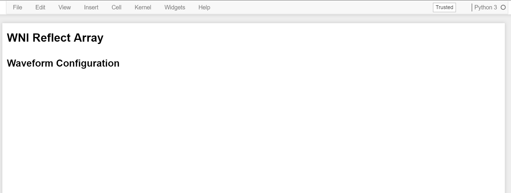
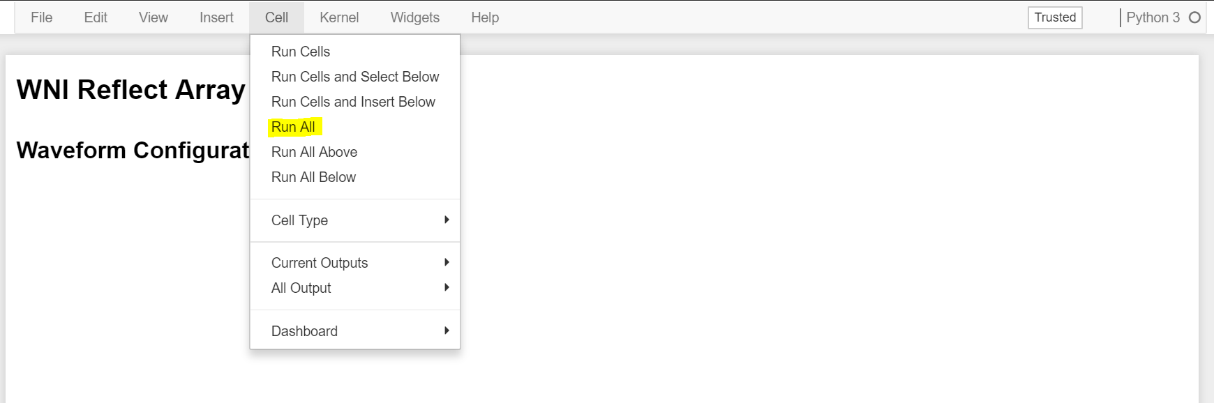
Click “Cell->Run All”. This will cause the UI to be populated.
Change the waveform and scan settings to whatever you want. See Configuring the Scan.
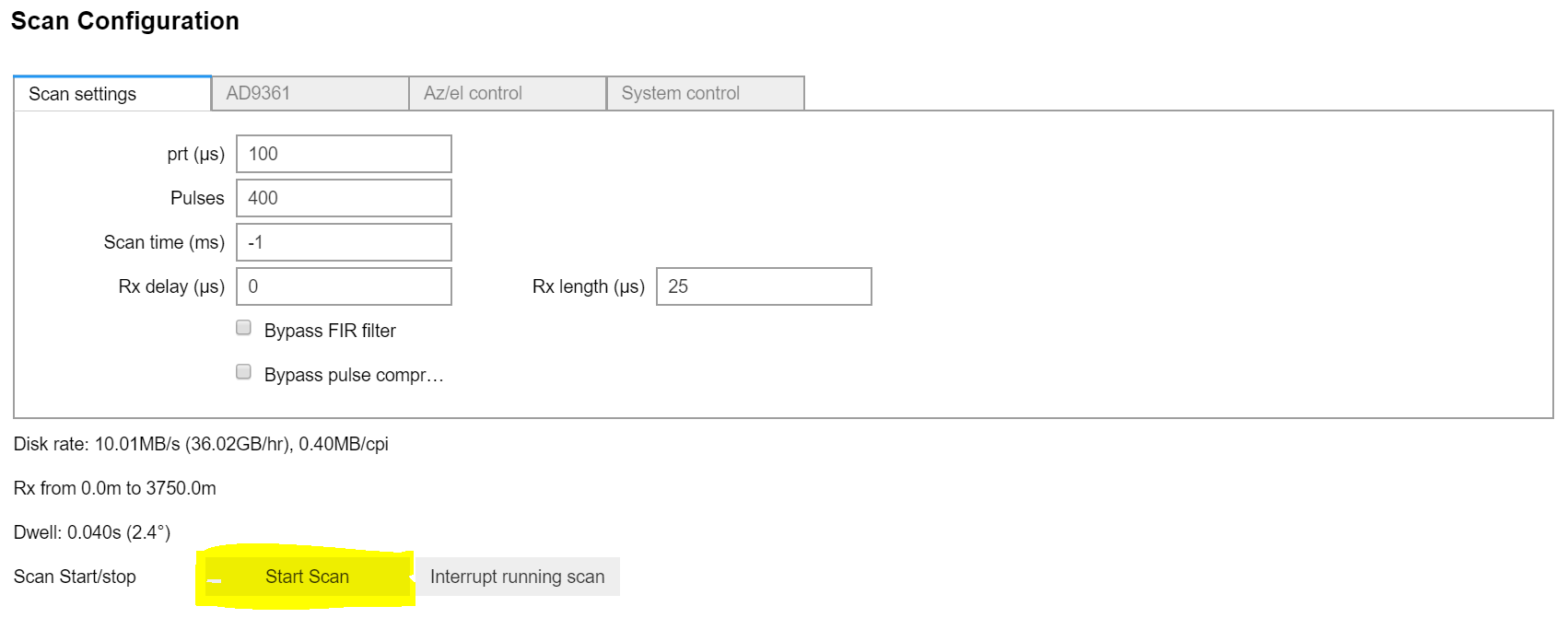
Click “Start Scan” to start the scan.
The radar is now producing data, and an application needs to be made to consume the data. See Creating a Client Program.
Warning
There is nothing that prevents multiple users from logging in to the radar user interface at once and making changes that conflict with each other. Ensure that no one else is logged in and using the radar before you begin making changes.
Configuring the Scan
Whenever the UI starts, it resets all configurations to the last used values. There are several things that need to be configured before a scan is run:
- Tx Waveforms (including dwell time)
- Scan settings (prt, rx length, etc.)
- Motor speed
- Actuator position
- System-level configuration
Transmit Waveform
The user interface supports transmitting LFM chirps, arbitrary I/Q samples, or disabling transmit on both channels independently. The user can select LFM Chirp, Arbitrary I/Q, or No Tx radio buttons in the Waveform menu.
Plots are provided to show the I/Q transmit samples, the frequency content, the autocorrelation of the Tx pulse, and the FIR coefficients and frequency response.
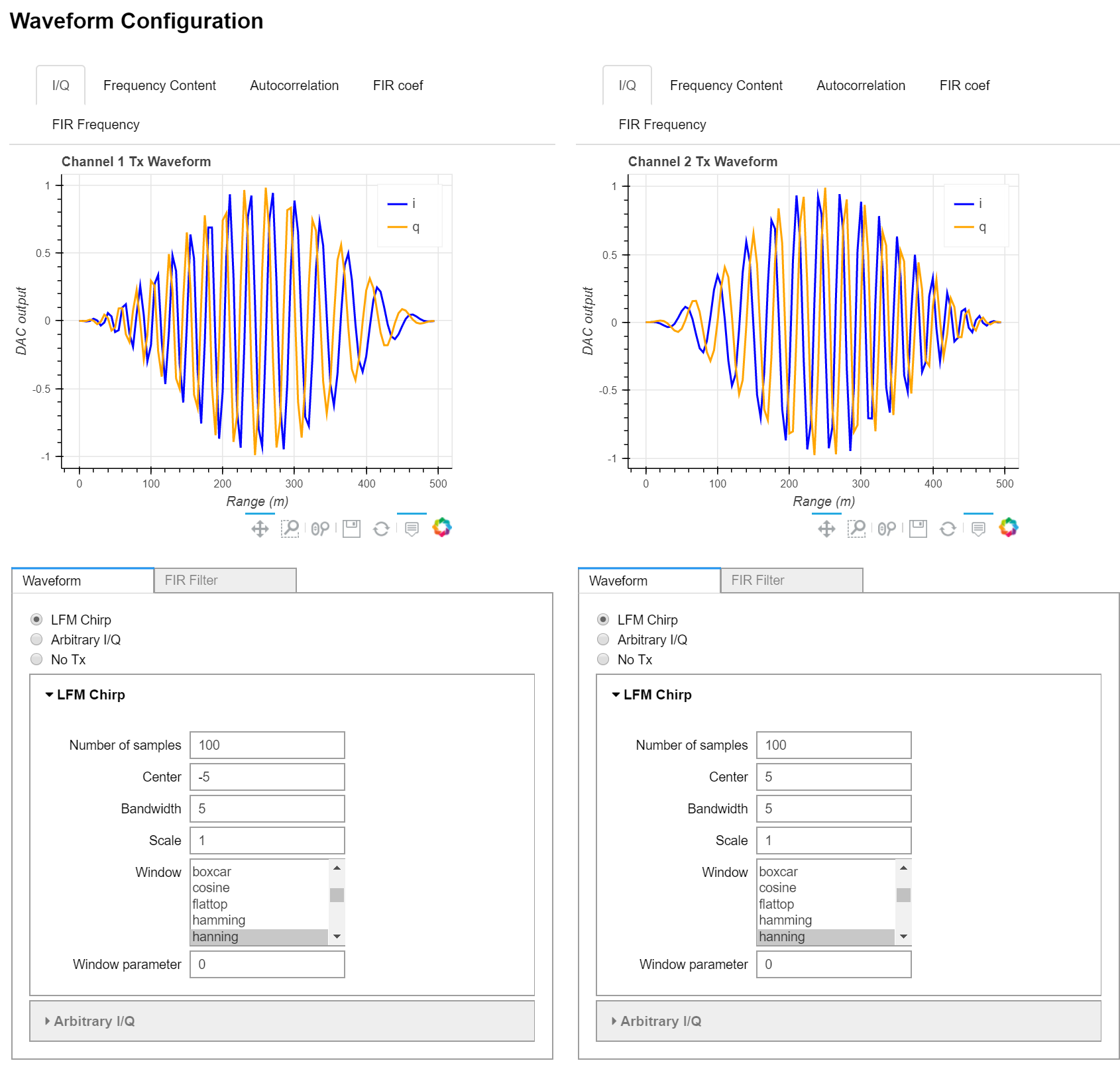
LFM Chirp
The user interface provides an easy way to specify a linear frequncy modulated transmit waveform, often simply called a chirp.
Number of samples: Number of Tx samples in the waveform. This setting is directly related to the pulse width: every sample is 1 / 30MHz long, so the pulse width is N * 33.33ns
Center: Center frequency of the LFM chirp, offset from 0.
Note
Setting the center frequency of the chirp to 0 can cause the AD9361 transceiver to have trouble calibrating. It is recommended to keep the Center frequency at about ±5 MHz.
Bandwidth: Chirp bandwidth. It is the user’s responsibility to ensure that the combination of bandwidth and center frequency settings do not cause aliasing. Since the sample clock is 30MHz, (center ± bandwidth/2) should be within [-15, 15] MHz.
Scale: An I/Q amplitude scale factor. In general, this should be set to 1. If a more attenuated signal is desired, it is better to change the attenuation in the AD9361 settings.
Window: The amplitude window to apply to the transmit waveform. It is necessary to have an amplitude window to keep range sidelobes at an acceptable level. Most windows supported by Scipy’s get_window function are available.
Window parameter: Certain window functions require a window parameter, e.g. the Tukey window takes a parameter between 0 and 1. If the selected window requires a parameter, it will be passed to the window functions.
Arbitrary I/Q
The user can also transmit arbitrary I/Q samples. This is less supported and may have bugs, but the adventurous user is welcome to try it.
- Waveform Name: The name of the waveform.
- I/Q: The I/Q samples to transmit. Every line in the text field should be
a complex number, e.g.
0.33 + 0.5j. Use the characterjto denote the imagincary component. - Normalized or Int12: Whether the complex samples given in the I/Q text field are normalized between [-1, 1] or the int12 values sent to the AD9361, between [-2048, 2047]
No Tx
The user may disable a channel by selecting “No Tx”. This causes the AD9361 to output only zeros.
FIR Filter
The Rx data coming from the transceiver goes through a complex FIR filter in the FPGA. This filter decimates the data by 6, so the Rx sample rate is effectively 5 MHz when the filter is active. The filter may also be bypassed in the Scan Settings menu. The user may select between a matched filter, bandpass filter, and arbitrary coefficient filter.
In normal operation, the FIR filter should be set to Matched Filter. However, the user may also set the filter to arbitrary real/complex values.
Matched Filter
This should be the normal mode of operation. When this is active, the complex FIR filters’ coefficients are set to make pulse compression happen in the FPGA.
Band pass
The FIR filter may be set as a band-pass filter. This is useful if the user would like to do receive only on the channel.
- Number of taps: the number of taps of the filter.
- Start band: The start band allowed through, in MHz. If this is set to 0, this is a lowpass filter.
- Stop band: The band to stop. If this is set to 15 MHz, this is a highpass filter.
- Window: window applied to the FIR coefficient samples. There is no support for windows with required parameters, e.g. a Tukey window is not supporte.
Arb
The user specifies the coefficients of the filter. The options are the same as transmit waveform arbitrary I/Q samples.
Scan Settings
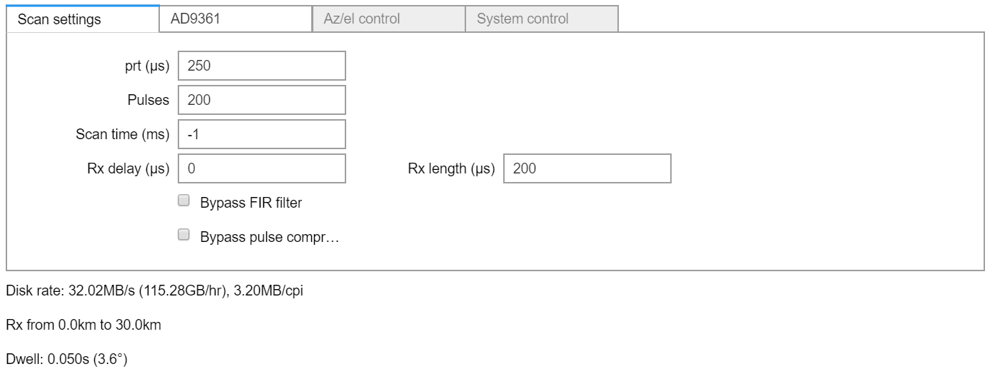
The scan settings menu allows you to change several aspects of a scan:
- prt: the pulse repetition time, in microseconds
- pulses: The number of pulses that will be coherently integrated together to form a radial.
- Scan time: the length of the scan, in milliseconds. If this is set to -1, the scan will run until it is interrupted by clicking the “Interrupt running scan” button.
- Rx delay: The beginning of the receive window in microseconds. This will generally be set to 0.
- Rx length: The length of the receive window in microseconds. This should always be set to less than the PRT. Some amount of buffer (10 microseconds at least) must be given between the PRT and the receive length due to implementation details in the FPGA.
- Bypass FIR: Whether to bypass the FIR filter in the FPGA. This should usually be unchecked.
- Bypass pulse compression: When the FIR filter in the FPGA is bypassed, pulse compression can be done on the processing computer. If this is unchecked and the “Bypass FIR” checkbox is checked, pulse compression will be done on the processing computer.
Additionally, some information is provided as scan settings are updated:
- Disk Rate: the data rate of Rx I/Q data.
- Rx length (in meters): where the data is actually looking.
- Dwell: How long it takes for a single radial to be generated, and how much angular distance this covers.
A few things to keep in mind:
- The prt, number of pulses, and rotation rate form the dwell time
- The rx_length + rx_delay must be less than the PRT.
- The transmit length is set in the Waveforms menu implicitly by the number of samples in the waveform. Remember that lowering the PRT increases the duty cycle.
AD9361 Settings
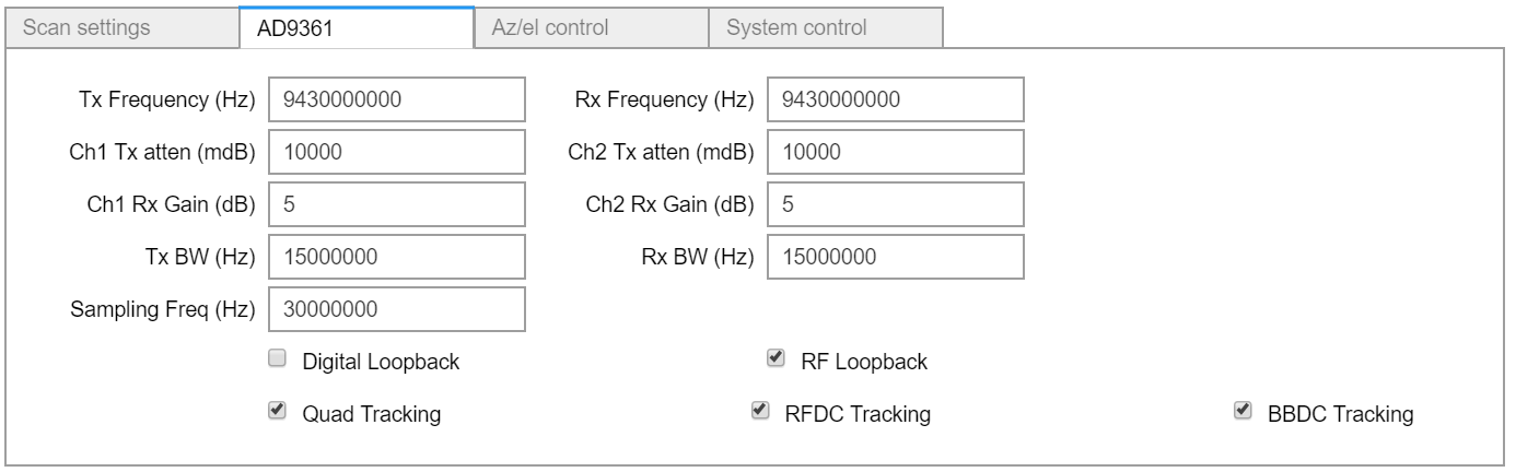
The AD9361 settings menu allows you to change configuration of the AD9361 transceiver to work with your application.
- Tx Frequency (Hz): The Transmit frequency of the radar, including any up/down conversion.
- Tx Frequency (Hz): The receive frequency of the radar, including any up/down conversion.
- Ch1 Rx Gain (dB): The Rx gain applied to the incoming signal in the Rx RF chain. This should be changed based on sensitivity and dynamic range requirements.
- Ch2 Rx Gain (dB): The Rx gain applied to the incoming signal in the Rx RF chain. This should be changed based on sensitivity and dynamic range requirements.
- Tx BW (Hz): The filters in the AD9361 are tuned to allow this bandwidth through the Tx chain.
- Rx BW (Hz): The filters in the AD9361 are tuned to allow this bandwidth through the Rx chain.
- Sampling Freq (Hz): The sampling frequency of the AD9361. This determines several system-level properties and should not be changed.
- Digital Loopback: Put the AD9361 into test mode where it does a digital loopback. This is useful only for debugging purposes.
- RF Loopback: This enables the RF loopback path on the carrier board the AD9361 sits on.
- Quad Tracking: Enables AD9361 quadrature tracking. This should normally be enabled.
- RFDC Tracking: Enables AD9361 RFDC tracking. This should normally be enabled.
- BBDC Tracking: Enables AD9361 BBDC tracking. This should normally be enabled.
Warning
The Sampling Frequency should not be changed unless some very serious debugging is going on.
Azimuth/Elevation Control
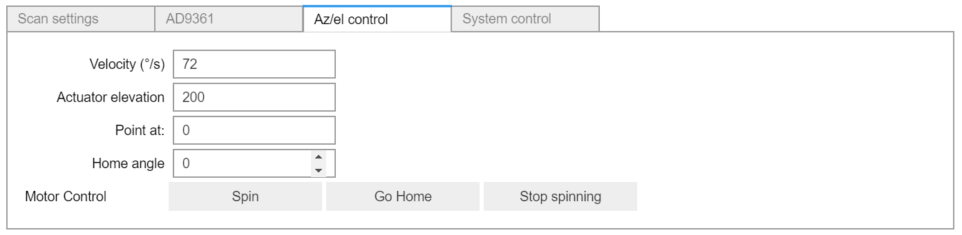
The Az/el control menu allows you to control the motor and the actuator.
- Velocity: Change the velocity that the motor spins at. If the radar is currently spinning, changing the velocity will have an immediate effect. Otherwise, it will take effect the next time the radar spins.
- Actuator Elevation: A number between 0 and 200. This is not yet calibrated with the actual elevation angle in degrees. An actuator position of 0 is the heighest the radar can point, and an actuator position of 200 is the lowest it can point.
- Point at:: Whenever the radar is not spinning, you can tell it to point at a specific angle by entering a number in this input. If the radar is spinning, this input is ignored.
- Home angle: The angle at which the radar is pointing after the
Go
Home
button is pressed. This is determined by the angle of an optical sensor mounted inside of the radome and the angle at which the radar is mounted. An angle of 0 degrees is North, and a positive angle is counter-clockwise.
There are a few buttons that are also available:
- Spin: Cause the motor to spin with the current settings.
- Go Home: Cause the motor to spin until its optical sensor is tripped. This should always be done whenever the motor is first started, and any time after the “Stop spinning” button is pressed.
- Stop spinning: Cause the motor to stop whatever it is doing. After the motor is stopped, it does not know its absolute position anymore, and the “Go Home” button must be pressed.
Note
There is currently no feedback given in the user interface about the angle that the radar is currently pointing or whether it is spinning or sitting still.
System Control
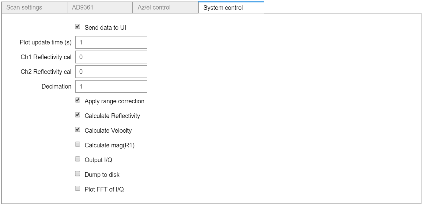
The system control menu allows you to change system-level settings and data flow options.
- Send data to UI: Send and plot data in the UI.
- Plot update time: How often to plot the data, in seconds. If this is too low, the system will become bogged down and become unresponsive.
- Ch1 Reflectivity cal: Calibration factor added to the range-corrected power to convert from power to Reflectivity on channel 1.
- Ch2 Reflectivity cal: Calibration factor added to the range-corrected power to convert from power to Reflectivity on channel 2.
- Decimation: If FIR filter is being bypassed, the processing computer can decimate the data by the factor specified here.
- Apply range correction: Apply range correction on reflectivity calculation. This is necessary for weather data.
- Calculate Reflectivity: Calculate and output reflectivity on the processing computer.
- Calculate Velocity: Calculate and output velociy on the processing computer.
- Calculate mag(R1): Calculate and output the magnitude of the lag1 autocorrelation of the returned data. For narrow-band returns, this can give better SNR than Reflectivity, but is generally not suitable for weather data.
- Output I/Q: Enable the processing computer to oitput all I/Q data. This can easily cause the radar to be unable to output all the data.
- Dump to disk: If this box is checked, the radar will dump I/Q data to a file on the radar. Because the size of the memory card on the radar is not very large, this should generally be left unchecked.
- Plot FFT of I/Q: Whether to plot the frequency content of the returned I/Q data. If the “Send data to UI” box is not checked, this does not do anything.
Running a Scan
When you have configured the scan with all the settings you require, run a scan by hitting the “Start Scan” button. This will cause the user interface to become disabled, exceptf for the “Interrupt running scan” button. Click the “Interrupt running scan” button to stop a running scan.